 PDF(15182 KB)

A Design Method of Vibration Accelerated Excitation Based on Feedback Approximate Damage
FENGYunwen, YANGRongji, XUEXiaofeng, LIUJiaqi, GAOTao
PDF(15182 KB)

Sponsored by: China Association for Science and Technology (CAST)
Editor-In-Chief: Xu Yida
ISSN 1000-1093
Hosted By: China Ordnance Society
Published By: Acta Armamentarii
CN 11-2176/TJ
PDF(15182 KB)
A Design Method of Vibration Accelerated Excitation Based on Feedback Approximate Damage
The method for formulating the high-acceleration profiles for electromechanical products has some problems,such as unclear correlation between key element of profile and excitation failure mechanism,low fault excitation efficiency,and high testing costs.To establish a correlation mechanism between the cumulative damage and the key elements of vibration test profile,a vibration acceleration excitation design method based on feedback approximate damage is proposed.The refined design of vibration test profile is achieved through the dynamic control of damage increment.By integrating the analysis of vibration damage mechanism and the frequency-domain analytical technology of power spectral density,the mapping relationship between vibration excitation and cumulative damage is quantified,and a vibration excitation-damage corresponding model (CM-VED) is established.The validity of the proposed method is verified by taking the high-acceleration step vibration test of a fuse as an example.The research findings indicate that the obtained high-acceleration vibration test profile enhances the excitation accuracy of failure limit by 60% compared with the standard fixed-step method,and the time is shortened by 33.33% compared with that of the equal division method while ensuring high excitation accuracy.The proposed CM-VED can provide a theoretical basis for establishing the correspondence between excitation and damage.The proposed vibration acceleration excitation design method based on feedback approximate damage can reduce the test cost while guaranteeing the excitation accuracy,providing technical support for the design of the high-acceleration vibration test profile of electromechanical products.
high-acceleration test / approximate damage / vibration excitation / profile design / quantitative mapping {{custom_keyword}} /

Table 1 Fault tree logic gates and event symbols表1 故障树逻辑门、事件符号 |
| 符号 | 名称 | 含义 |
|---|---|---|
 | 或门 | 输入端只要有一个事件出现时即有输出 |
 | 基本事件 | 导致顶事件发生的最基本的或不能再向下分析的原因,是底事件的一种 |
 | 结果事件 | 由其他事件或事件组合导致的事件,分为顶事件和中间事件 |
Table 2 Analyed results of large capacitance stress and cumulative damage表2 大电容应力、累积损伤分析结果 |
| 振动载荷/ Grms | 元器件最大等效应力值/MPa | 各级载荷下的 损伤 | ||
|---|---|---|---|---|
| 1σ | 2σ | 3σ | ||
| 5 | 20.3 | 40.6 | 60.9 | 1.059×10⁻⁴ |
| 8 | 32.6 | 65.2 | 97.8 | 1.799×10⁻³ |
| 11 | 44.8 | 89.6 | 134.4 | 0.0120 |
| 14 | 56.9 | 113.8 | 170.7 | 0.0503 |
| 17 | 69.2 | 138.4 | 207.6 | 0.1620 |
| 20 | 81.5 | 163.0 | 244.5 | 0.4310 |
| 21 | 85.5 | 171.0 | 256.5 | 0.5740 |
| 22 | 89.6 | 179.2 | 268.8 | 0.7600 |

Fig.9 Design of appearance and internal structural modules of a certain fuse图9 某型引信外观及内部结构模块设计 |
Table 3 Corresponding table of internal structure module component names表3 内部结构模块元器件 |
| 标号 | 元器件名称 | 标号 | 元器件名称 |
|---|---|---|---|
| A | 场控晶闸管(MOS Controlled Thyristor,MCT) | G | 电压比较器b |
| B | 金属氧化物半导体场效应晶体管(Metal Oxide Semiconductor Field Effect Transistor,MOSFET) | H | 二极管 |
| C | 电压比较器a | I | 贴片电阻 |
| D | A/D转换器 | J | 变压器 |
| E | 信号调理器 | K | 陶瓷电阻 |
| F | 升压芯片、降压芯片 | L | 三极管 |
Table 4 Analysis table for fault modes of a certain fuze表4 某型引信故障模式分析表 |
| 故障 模式 | 局部 影响 | 最终 影响 | 故障原因 | 串联元器件类型 |
|---|---|---|---|---|
| 电压 变换 异常 | 高压点 火电路 不能正 常点火 | 引信 瞎火 | 高压变化 单元异常 | 变压器、二极管、贴片电阻、升压芯片 |
| 反馈控制 单元异常 | MCT、比较电路芯片a、A/D转换器、信号调理器 | |||
| 发火 储能 不足 | 雷管 无法 起爆 | 引信 瞎火 | 储能电路 单元异常 | 贴片电阻、二极管、三极管 |
| 起爆触发 单元异常 | 陶瓷电阻、MOSFET、比较电路芯片b |
Table 5 Maximum equivalent stress and damage value of large ceramic resistor pin (x-axis)表5 大陶瓷电阻管脚最大等效应力、损伤值(x轴) |
| 振动载荷/ Grms | 元器件最大等效应力值/MPa | 各级载荷 下的损伤 | 合计损 伤值 | ||
|---|---|---|---|---|---|
| 1σ | 2σ | 3σ | |||
| 5 | 17.136 | 34.272 | 51.408 | 3.840×10⁻⁵ | 0.768 |
| 10 | 34.295 | 68.590 | 102.885 | 0.00240 | |
| 15 | 51.439 | 102.878 | 154.317 | 0.0275 | |
| 20 | 68.590 | 137.180 | 205.770 | 0.154 | |
| 25 | 85.744 | 171.488 | 257.232 | 0.584 | |
| 30 | 102.890 | 205.780 | 308.670 | 1.738 | 2.510 |
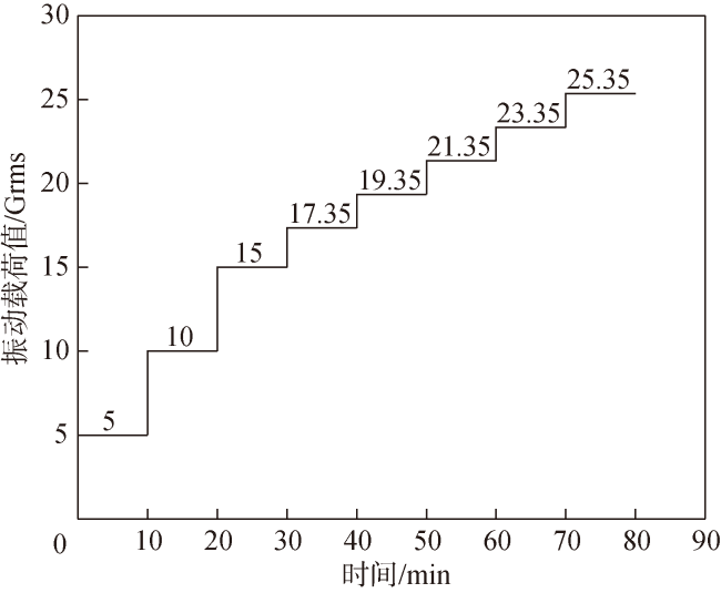
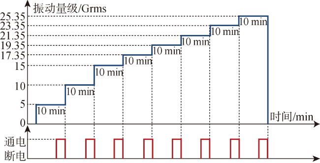
Fig.14 Test profile designed by feedback approximation damage method图14 反馈近似损伤法设计的试验剖面图 |
Table 6 Profile step division of feedback approximate damage method表6 反馈近似损伤法剖面步长划分 |
| 步进顺序 | 振动载荷/Grms | 各级载荷下的损伤 | 合计损伤值 |
|---|---|---|---|
| 1 | 5.00 | 3.865×10⁻⁵ | 0.839 |
| 2 | 10.00 | 0.00240 | |
| 3 | 15.00 | 0.0276 | |
| 4 | 17.35 | 0.0659 | |
| 5 | 19.35 | 0.1270 | |
| 6 | 21.35 | 0.2280 | |
| 7 | 23.35 | 0.3890 | |
| 8 | 25.35 | 0.6360 | 1.468 |
Table 7 Test vibration load and test results表7 试验振动载荷与测试结果 |
| 步进顺序 | 试验振动载荷/Grms | 步长/Grms | 测试结果 |
|---|---|---|---|
| 1 | 5 | 5 | 正常 |
| 2 | 10 | 5 | 正常 |
| 3 | 15 | 5 | 正常 |
| 4 | 17.35 | 2.35 | 正常 |
| 5 | 19.35 | 2 | 正常 |
| 6 | 21.35 | 2 | 正常 |
| 7 | 23.35 | 2 | 正常 |
| 8 | 25.35 | 2 | 异常 |
| 9 | 23.35 | -2 | 异常 |
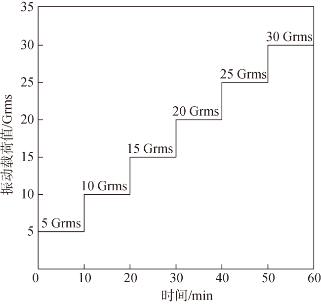
Table 8 Divided profile step size of standard fixed step method表8 标准固步法剖面步长划分 |
| 步进顺序 | 振动载荷/Grms | 各级载荷下的损伤 | 合计损伤值 |
|---|---|---|---|
| 1 | 5 | 3.840×10⁻⁵ | 0.768 |
| 2 | 10 | 0.00240 | |
| 3 | 15 | 0.0275 | |
| 4 | 20 | 0.1540 | |
| 5 | 25 | 0.5840 | |
| 6 | 30 | 1.7380 | 2.510 |
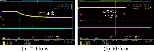
Table 9 Test vibration load and test results of standard fixed step method表9 标准固步法试验振动载荷与测试结果 |
| 步进顺序 | 试验振动载荷/Grms | 步长/Grms | 测试结果 |
|---|---|---|---|
| 1 | 5 | 5 | 正常 |
| 2 | 10 | 5 | 正常 |
| 3 | 15 | 5 | 正常 |
| 4 | 20 | 5 | 正常 |
| 5 | 25 | 5 | 正常 |
| 6 | 30 | 5 | 异常 |
| 7 | 25 | -5 | 异常 |
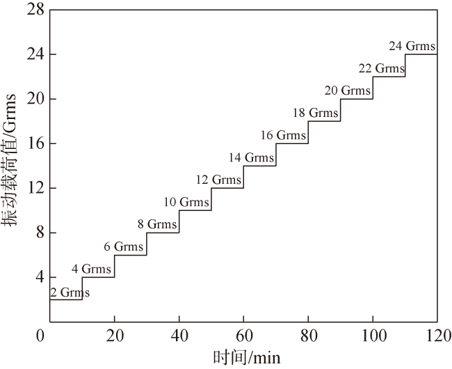
Table 10 Divided profile step size of the averaging method表10 均分法剖面步长划分 |
| 步进顺序 | 振动载荷/Grms | 各级载荷下的损伤 | 合计损伤值 | |
|---|---|---|---|---|
| 1 | 2 | 1.613×10⁻⁷ | 0.578 | |
| 2 | 4 | 1.018×10⁻⁵ | ||
| 3 | 6 | 0.000110 | ||
| 4 | 8 | 0.000640 | ||
| 5 | 10 | 0.00243 | ||
| 6 | 12 | 0.00725 | ||
| 7 | 14 | 0.0182 | ||
| 8 | 16 | 0.0405 | ||
| 9 | 18 | 0.0820 | ||
| 10 | 20 | 0.154 | ||
| 11 | 22 | 0.272 | ||
| 12 | 24 | 0.458 | 1.036 | |
Table 11 Vibration load and test results of the equal distribution method test表11 均分法试验振动载荷与测试结果 |
| 步进顺序 | 试验振动载荷/Grms | 步长/Grms | 测试结果 |
|---|---|---|---|
| 1 | 2 | 2 | 正常 |
| 2 | 4 | 2 | 正常 |
| 3 | 6 | 2 | 正常 |
| 4 | 8 | 2 | 正常 |
| 5 | 10 | 2 | 正常 |
| 6 | 12 | 2 | 正常 |
| 7 | 14 | 2 | 正常 |
| 8 | 16 | 2 | 正常 |
| 9 | 18 | 2 | 正常 |
| 10 | 20 | 2 | 正常 |
| 11 | 22 | 2 | 正常 |
| 12 | 24 | 2 | 异常 |
| 13 | 22 | -2 | 异常 |
Table 12 Comparison of step size division methods表12 步长划分方法对比 |
| 序号 | 方法 | 步长/Grms | 破坏极限区间/Grms | 激发精度对比 | 总时间/min | 总时间对比 | 故障部位 |
|---|---|---|---|---|---|---|---|
| 1 | 反馈近似损伤法 | 5;2.35;2 | [23.35,25.35] | 80 | 大陶瓷电阻 | ||
| 2 | 标准固步法 | 5 | [25,30] | 1对比2:60% | 60 | 1对比2:-33% | 大陶瓷电阻 |
| 3 | 均分法 | 2 | [22,24] | 1对比3:0 | 120 | 1对比3:33% | 大陶瓷电阻 |
| [1] |
{{custom_citation.content}}
{{custom_citation.annotation}}
|
| [2] |
魏冰阳, 郭玉梁, 古德万, 等. 弧齿锥齿轮弯曲疲劳寿命仿真与加速试验评价[J]. 兵工学报, 2022, 43(11):2945-2952.
疲劳寿命试验是齿轮强度评价必不可少的手段,但长期以来弧齿锥齿轮疲劳试验数据缺乏,导致相关产品设计存在较大的不确定性。本文建立了弧齿锥齿轮三维有限元模型,给出了相应的弯曲疲劳寿命仿真计算流程;探讨了加速疲劳试验的机理与方法,确定了加速疲劳试验应力因子。对20CrNiMo材料试棒进行了拉伸疲劳强度试验,获得了材料的S-N曲线,以此为基础数据,利用三维有限元软件完成了两个水平的弯曲疲劳寿命仿真计算;在专用闭功率流耐久性试验台上进行了若干组齿轮的弯曲强度疲劳寿命试验,疲劳寿命与理论仿真结果对比误差小于3.2%,一致性较好。证明了以疲劳寿命仿真与加速试验手段评价复杂结构件锥齿轮弯曲疲劳强度的可行性。
Fatigue life testing is an indispensable method for evaluating the gear strength of spiral bevel gears, but the lack of fatigue test data has long led to high uncertainties in the design of related products. This study establishes a three-dimensional finite element model for a spiral bevel gear and presents a simulation calculation of the corresponding bending fatigue life. The mechanism and methods of the accelerated fatigue test are discussed, and the stress factors for the accelerated test are presented. The tensile fatigue strength test is carried out on the 20CrNiMo material test bar, and the S-N curve of the material is obtained. Based on this, a three-dimensional finite element software is used to complete multiple calculations of simulated digital bending fatigue life in a special closed power flow bevel gear. The durability test bench has been used to conduct several sets of tests on gear bending strength and fatigue life. Test results and theoretical simulation results are in good agreement, with a comparison error of less than 3.2%. Through fatigue life simulation and accelerated testing, the feasibility of the evaluation method is proved. The approach works well in evaluating the bending fatigue strength of bevel gears with complex structures.
{{custom_citation.content}}
{{custom_citation.annotation}}
|
| [3] |
{{custom_citation.content}}
{{custom_citation.annotation}}
|
| [4] |
赵晓东, 穆希辉. 加速度计贮存试验及寿命评估方法研究[J]. 兵工学报, 2020, 41(6):1227-1235.
针对长期贮存后加速度计寿命难以评估的问题,提出一种综合利用加速试验数据与自然贮存试验数据的评估方法。采用极小卡方估计和拟合优度检验,处理加速度计的自然贮存数据,得到其可能服从的4种寿命分布函数,确定加速度计寿命分布形式为威布尔分布和Ⅰ型极大值分布;基于加速度计的先验信息,设计并开展加速度计的步进加速寿命试验,获得加速度计的加速失效数据;在威布尔分布和I型极大值分布假设下,依据加速失效数据估计加速度计寿命分布模型参数,采取加速因子变异系数的方法,选定Ⅰ型极大值分布为加速度计的寿命分布函数,得出常规应力水平下可靠度0.90和0.95的寿命分别为14.917 6 a和10.052 4 a. 通过对比标准贮存环境中和寿命分布模型中加速度计的失效比率,验证了综合利用两种试验数据评估加速度计寿命方法的有效性。
Aiming at the problem that the life of accelerometers is difficult to evaluate after long-term storage, an evaluation method that comprehensively uses accelerated test data and natural storage test data was proposed. The minimum Chi-square estimation and goodness-of-fit test was used, the accelerometer's natural storage data was processed to obtain the four life distribution functions that it may obey, and the accelerometer life distribution was determined as Weibull distribution and type Ⅰ maximum distribution; With reference to the a priori information of the accelerometer, a step-by-step acceleration life test of the accelerometer is designed and carried out to obtain acceleration failure data of the accelerometer; under the assumptions of Weibull distribution and type Ⅰ maximum value distribution, the parameters of the accelerometer life distribution model are estimated based on accelerated failure data, and the method of acceleration factor variation coefficient is used to select the type Ⅰ maximum value distribution as the life distribution function of the accelerometer. The lifespan of reliability 0.90 and 0.95 under conventional stress level is 14.917 6 a and 10.052 4 a, respectively. By comparing the failure rate of accelerometers in the standard storage environment and the life distribution model, the effectiveness of using two test data to evaluate the lifespan of the accelerometer is verified. Key
{{custom_citation.content}}
{{custom_citation.annotation}}
|
| [5] |
WANG,
{{custom_citation.content}}
{{custom_citation.annotation}}
|
| [6] |
{{custom_citation.content}}
{{custom_citation.annotation}}
|
| [7] |
孙树磊, 雷丽妃, 黄海波, 等. 基于用户作业工况的履带式挖掘机加速疲劳强化路面构建方法[J]. 机械工程学报, 2022, 58(16):319-328.
为提高挖掘机疲劳强度安全可靠性,解决挖掘机用户作业工况及加速疲劳试验方法缺乏等问题,以挖掘机油箱为研究对象,基于等效损伤原则,通过用户工况调研、采石场试验测试、虚拟路面构建、多体动力学仿真、强化路面试验验证及疲劳损伤计算等一系列流程,提出一种基于挖掘机用户作业工况的履带式挖掘机加速疲劳强化路面构建方法。结果表明,采用爬碎石坡等共9种采石场试验测试工况表征用户作业工况,可获得量化的工况测试数据及目标总损伤;基于多体动力学构建的挖掘机动力学仿真模型及虚拟强化路面计算结果与真实强化路面试验测试结果较为吻合;基于该方法获得了与目标总损伤一致的多种不同的强化路面及不同档位速度组合工况,其中由0.3 m凸块间距1档、2 m凸块间距1档及15 m凸块间距1档3种工况所构成的强化路面组合工况较优,强化系数为15.1,该方法可大幅度降低挖掘机整机及关键零部件的疲劳试验时间。
In order to improve the fatigue strength safety and reliability of excavators, and solve the problems of the lack of the excavator user operating conditions and accelerated fatigue test methods, a construction method for accelerated fatigue reinforced pavement of crawler excavator based on user operating conditions is proposed with the excavator fuel tank as the research object, through a series of processes such as user condition investigation, quarry test, virtual pavement construction, multi-body dynamics simulation, reinforced pavement test verification and fatigue damage calculation. The results show that: 9 quarry test conditions including climbing gravel slopes, and the quantified test data and target total damage are obtained. The excavator dynamics simulation model constructed based on multi-body dynamics and the calculation results of the virtual reinforced pavement are more consistent with the test results of the real enhanced pavement. Based on this method, a variety of different reinforced pavements and different gear speed combinations consistent with the target total damage are obtained. The operating condition composed of bumps interval 0.3 m and gear 1, bumps interval 2 m and gear 1, and bumps interval 15 m and gear 1 is better, and the intensified coefficient is 15.1. This method can be used for greatly reducing fatigue test time of the excavator and the key parts.
{{custom_citation.content}}
{{custom_citation.annotation}}
|
| [8] |
{{custom_citation.content}}
{{custom_citation.annotation}}
|
| [9] |
{{custom_citation.content}}
{{custom_citation.annotation}}
|
| [10] |
{{custom_citation.content}}
{{custom_citation.annotation}}
|
| [11] |
{{custom_citation.content}}
{{custom_citation.annotation}}
|
| [12] |
{{custom_citation.content}}
{{custom_citation.annotation}}
|
| [13] |
薛小锋, 徐光铎, 冯蕴雯, 等. 基于元件降额设计的温度步进强化试验剖面设计[J]. 系统工程与电子技术, 2023, 45(12):4073-4083.
针对目前强化试验剖面效率低、成本高的问题, 提出了某型弹类电子产品温度强化试验剖面设计框架。结合产品可靠性框图对试验对象进行失效逻辑分析, 基于元器件降额的步长设计方法(step design method based on component derating, CD-SDM)优化步长、缩短试验时间, 采用基于有限元仿真的确定性分析方法获得工作极限和破坏极限估值, 降低步长划分时极限间工作裕度的影响, 实现步长、试验时间和其他要素的优化。以某型弹类电子产品高温步进为例验证所提方法, 结果表明获得的温度强化试验剖面较传统方法在试验时间上最少可缩短13.33%左右, 与传统方法相比减少了1/4的检测次数, 优化了目前可靠性强化试验剖面设计对弹类电子产品试验效率低、成本高的问题。
{{custom_citation.content}}
{{custom_citation.annotation}}
|
| [14] |
姬亚萌, 张卫正, 原彦鹏, 等. 高强化柴油机活塞加速热疲劳与等效寿命评估方法[J]. 兵工学报, 2022, 43(12):3008-3019.
{{custom_citation.content}}
{{custom_citation.annotation}}
|
| [15] |
{{custom_citation.content}}
{{custom_citation.annotation}}
|
| [16] |
{{custom_citation.content}}
{{custom_citation.annotation}}
|
| [17] |
{{custom_citation.content}}
{{custom_citation.annotation}}
|
| [18] |
{{custom_citation.content}}
{{custom_citation.annotation}}
|
| [19] |
{{custom_citation.content}}
{{custom_citation.annotation}}
|
| [20] |
{{custom_citation.content}}
{{custom_citation.annotation}}
|
| [21] |
{{custom_citation.content}}
{{custom_citation.annotation}}
|
| [22] |
{{custom_citation.content}}
{{custom_citation.annotation}}
|
| [23] |
{{custom_citation.content}}
{{custom_citation.annotation}}
|
| [24] |
{{custom_citation.content}}
{{custom_citation.annotation}}
|
| [25] |
郭伟超, 赵怀山, 李成, 等. 基于小波包能量谱与主成分分析的轴承故障特征增强诊断方法[J]. 兵工学报, 2019, 40(11):2370-2377.
滚动轴承出现损伤时,采集的振动信号呈非平稳性,采用一般的时域和频域分析方法不能准确提取出振动信号的故障特征。根据小波包多分辨、精细化的分解特性,提出一种基于小波包能量谱与主成分分析(PCA)方法的滚动轴承故障诊断算法。将振动信号进行小波包分解,得到重点频率段信息的能量谱,提取能量谱作为特征向量;利用PCA方法对特征向量降维并减小噪声信号的干扰,获得增强的故障特征;利用层次聚类方法和改进的模糊c均值聚类算法对不同类型的滚动轴承故障进行识别,两种聚类方法都准确地识别出了不同的故障类型。实例验证结果表明,所提方法能够有效地提取振动信号中的有用故障特征,实现轴承故障类型的精确诊断。
{{custom_citation.content}}
{{custom_citation.annotation}}
|
| [26] |
{{custom_citation.content}}
{{custom_citation.annotation}}
|
| [27] |
杨彦彰, 朱建华, 张华, 等. 电工电子产品加速应力试验规程高加速寿命试验导则:GB/T 29309—2012[S]. 北京: 工业和信息化部, 2012.
{{custom_citation.content}}
{{custom_citation.annotation}}
|
| [28] |
{{custom_citation.content}}
{{custom_citation.annotation}}
|
| [29] |
程祥利, 刘波, 赵慧. 侵彻战斗部-引信系统动力学建模与仿真[J]. 兵工学报, 2020, 41(4):625-633.
为揭示侵彻过程中引信电路模块的动态响应机理,将机械振动理论引入侵彻过程理论分析与计算,提出一种简化的侵彻战斗部-引信系统动力学模型。以侵彻战斗部-引信系统的载荷传递关系为基础,基于多自由度弹簧-质量-阻尼系统建立模型的动力学微分方程;通过谐响应分析确定固有频率、阻尼比等动力学参数,并采用数值积分的方法预测不同侵彻工况下的响应特性;从系统幅频响应特性的角度分析响应特性与传统经验公式解有很大差异的原因。与谐响应分析结果、火炮试验实测过载信号的对比分析表明:提出的动力学模型能准确、快速地预测战斗部、引信在侵彻过程中的响应特性;考虑轴向振动后,侵彻战斗部表现出明显的振动放大特性与周期振荡特性,而且是影响引信电路模块响应特性的首要因素。
The mechanical vibration theory is introduced into theoretical analysis and calculation of penetration process, and a simplified dynamic model of penetration warhead-fuze system is proposed with the purpose of revealing the dynamic response mechanism of circuit module of fuze in penetration process. On the basis of analysis of loading transfer relation, a dynamic differential equation is established based on multi-DOFs spring-mass-damper system, and the dynamic parameters, such as natural frequency and damping ratio, are determined by the harmonic response analysis. Then the dynamic characteristics under different penetration conditions are predicted by numerical integration method, and the reason why the predicted dynamic characteristics differ greatly from the calculated result of the traditional empirical formula is analyzed from the amplitude-frequency response.The credibility of the proposed model was verified through artillery test, and the overload signal in penetration process was collected. The calculated value of overload signal is in agreement well with measured result. The result shows that the proposed model is more suitable to predict the dynamic characteristics of warhead or fuze in penetration process. It is shown that penetration warhead exhibits obvious vibration amplificatory characteristics and periodic oscillation characteristics in considering the axial vibration effect, and the dynamic characteristics of warhead are the most important factor affecting the dynamic characteristics of circuit module in fuze.Key
{{custom_citation.content}}
{{custom_citation.annotation}}
|
| [30] |
邱士起. 冲击作用下引信起爆控制系统关键元器件失效机理及其可靠性分析[D]. 北京: 北京理工大学, 2016:53-68.
{{custom_citation.content}}
{{custom_citation.annotation}}
|
| [31] |
{{custom_citation.content}}
{{custom_citation.annotation}}
|
| [32] |
{{custom_citation.content}}
{{custom_citation.annotation}}
|
| [33] |
杨硕, 杜天玮, 张晓鹏, 等. 外物损伤对叶片振动疲劳裂纹扩展性能的影响[J]. 兵工学报, 2023, 44(6):1713-1721.
In order to study the effect of foreign object damage (FOD) on the fatigue crack propagation of aero-engine blades, using the drop weight impact testing equipment, the FOD simulation test and vibration fatigue test of TC4 titanium alloy specimens were carried out under different impact energies. The relationship between the crack length and fatigue life of the damaged specimens was obtained, and the parameters of fatigue fracture crack morphology were fitted to establish a fatigue crack growth prediction and calculation model. The results showed that: The depth and width of the notch decreased nonlinearly with the decrease of impact energy; when the impact energy is large, the fatigue crack propagates first along the bending microcrack and then along the straight line; when the impact energy is small, the fatigue crack of the specimen keeps linear propagation; the crack initiation life is related to both impact energy and stress level. {{custom_citation.content}}
{{custom_citation.annotation}}
|
| [34] |
{{custom_citation.content}}
{{custom_citation.annotation}}
|
| [35] |
马岩. 航天精密机电组件高加速筛选试验模拟与仿真[D]. 西安: 西安电子科技大学, 2016:28-32.
{{custom_citation.content}}
{{custom_citation.annotation}}
|
| [36] |
徐保荣, 王涛, 梁梓. 基于操纵动作预测的履带车辆载荷谱编制方法与流程[J]. 兵工学报, 2022, 43(2):252-259.
A new generating method of load spectrum for tracked vehicles is proposed based on load spectrum blocks and training subjects to cope with the problem of insufficient sample size. Action of vehicles and driving behavior are predicted by using path planning algorithm and action planning algorithm. Training subjects and geographic information are used as input data, the predicted vehicle situation and driving behavior are taken as indexes to get load spectrum blocks, and the time domain load spectrum are generated by spliced load spectrum blocks. The verification test results show that the load data samples generated by splicing method can reflect the vehicle working conditions correctly, and it can be used to generate load samples rapidly.
{{custom_citation.content}}
{{custom_citation.annotation}}
|
| {{custom_ref.label}} |
{{custom_citation.content}}
{{custom_citation.annotation}}
|
PDF(15182 KB)
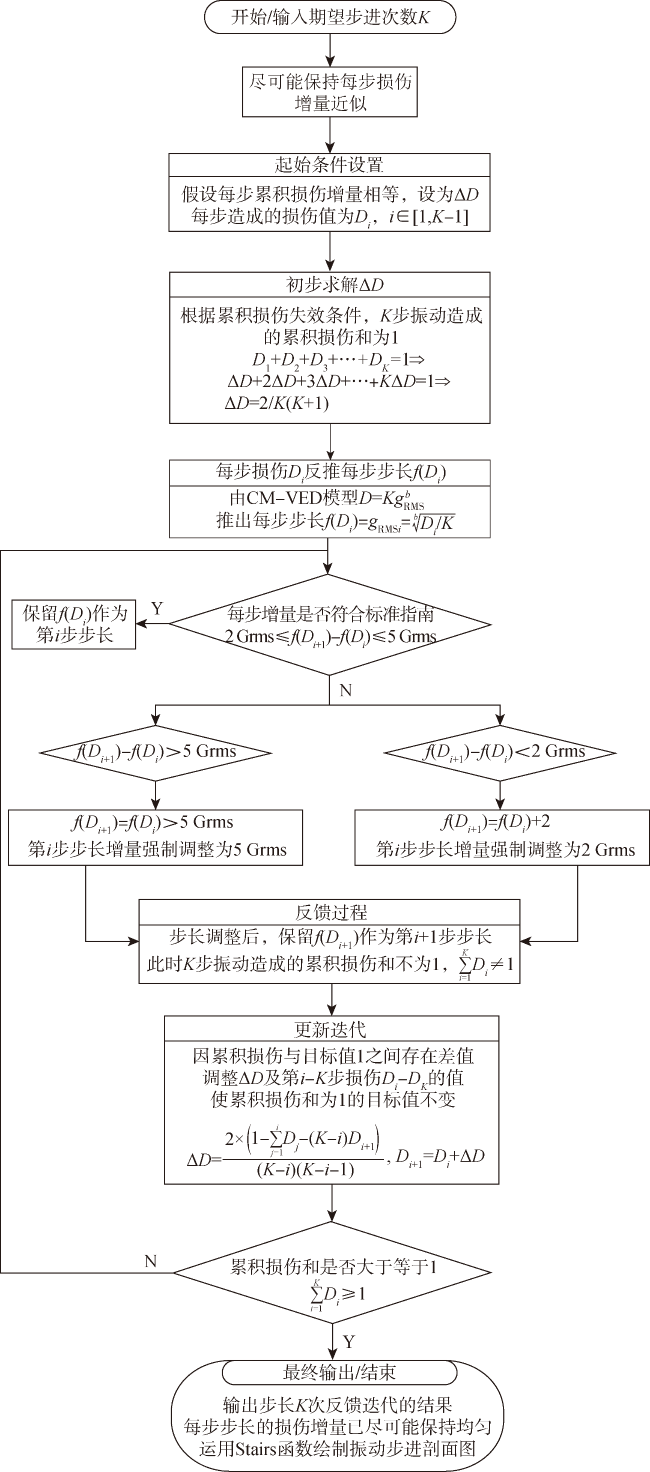
 Fig.1 CM-VED modelFig.2 Change trend of damage increment in each stage of high-acceleration testFig.3 Feedback approximate damage methodFig.4 Design process of vibration acceleration excitation based on feedback approximate damageFig.5 Fault tree of a certain fuse detonation system
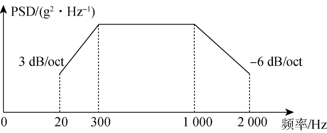
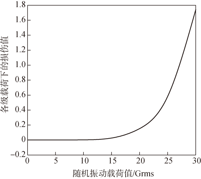
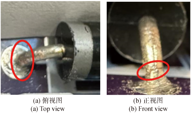
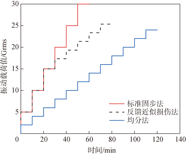
 Table 1 Fault tree logic gates and event symbolsTable 2 Analyed results of large capacitance stress and cumulative damageFig.6 Comparison chart between accumulated damage data of large capacitors and CM-VEDFig.7 Process of designing the profile step size by feedback approximate damage methodFig.8 Design framework for vibration HALT test profileFig.9 Design of appearance and internal structural modules of a certain fuseTable 3 Corresponding table of internal structure module component namesFig.10 Reliability block diagram of a certain fuzeTable 4 Analysis table for fault modes of a certain fuzeFig.11 Vibration power spectral density curveFig.12 Equivalent stress cloud map of fuze under 20Grms load along x-axisTable 5 Maximum equivalent stress and damage value of large ceramic resistor pin (x-axis)Fig.13 CM-VED of a certain fuseFig.14 Test profile designed by feedback approximation damage methodTable 6 Profile step division of feedback approximate damage methodFig.15 Vibration HALT test of a certain fuseFig.16 Vibration step test profileFig.17 Product test results under non-vibration conditionsFig.18 x axis vibration HALT test fuse discharge curveTable 7 Test vibration load and test resultsFig.19 Cracks in the pins of large ceramic resistors caused by vibration testsTable 8 Divided profile step size of standard fixed step methodFig.20 Experimental profile designed using standard fixed step methodFig.21 Discharge curve of vibration HALT test fuse under standard fixed step profileTable 9 Test vibration load and test results of standard fixed step methodFig.22 Cracks in the pins of large ceramic resistors caused by standard fixed step vibration testTable 10 Divided profile step size of the averaging methodFig.23 Experimental profile designed using the averaging methodFig.24 Discharge curve of vibration HALT test fuse under the uniform distribution method profileTable 11 Vibration load and test results of the equal distribution method testFig.25 Cracks in the pins of large ceramic resistors caused by vibration testing using the equal distribution methodTable 12 Comparison of step size division methodsFig.26 Profile step curves of three methods
/
| 〈 |
|
〉 |


